-
Country / Region
-
Albania

-
Armenia

-
Austria

-
Azerbaijan

-
Belarus

-
 Belgium
 -
Bosnia Herzegovina

-
Bulgaria

-
Croatia

-
Cyprus

-
Czech Republic

-
Denmark

-
Estonia

-
Europe

-
Finland

-
France

-
Georgia

-
Germany

-
 Greece
 -
Hungary

-
Iceland

-
Ireland

-
Israel

-
Italy

-
Kazakhstan

-
Kosovo

-
Kyrgyzstan

-
Latvia

-
Lithuania

-
Luxembourg

-
Macedonia

-
Malta

-
Moldova

-
Montenegro

-
Netherlands

-
Norway

-
 Poland
 -
Portugal

-
 Romania
 -
 Russia
 -
Serbia

-
Slovakia

-
Slovenia

-
Spain

-
Sweden

-
Switzerland

-
Tajikistan

-
Turkey

-
Turkmenistan

-
 Ukraine
 -
United Kingdom

-
Uzbekistan

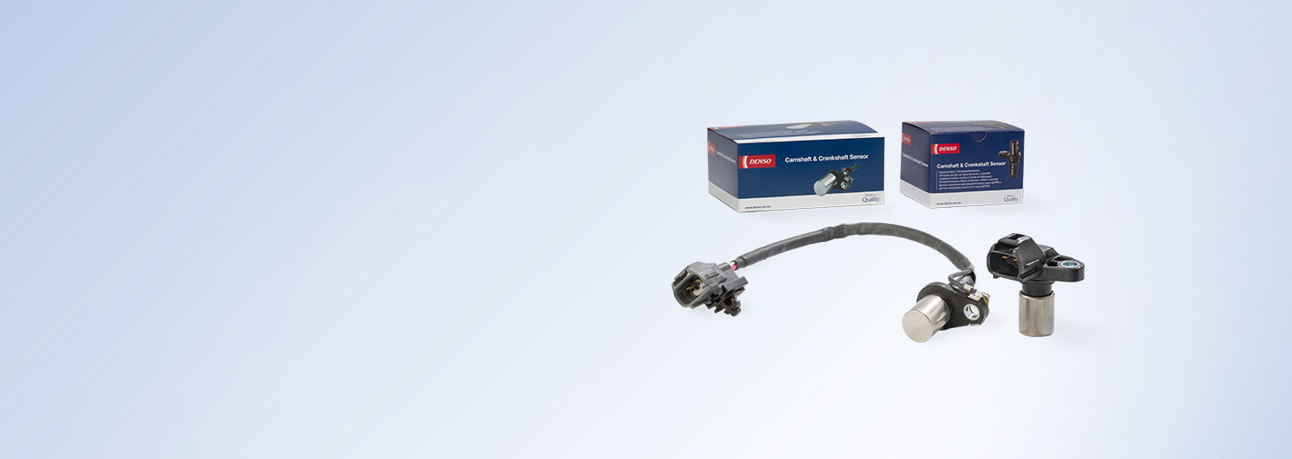
Camshaft and crankshaft sensors
Camshaft and crankshaft sensors keep ignition timing, engine speed and cylinder firing times synchronized, allowing the engine to run smoothly.
Camshaft and crankshaft sensors
How camshaft and crankshaft sensors work
These two types of sensor help the electrical control unit (ECU) calculate the position of two key parts of the engine: the camshaft and the crankshaft.
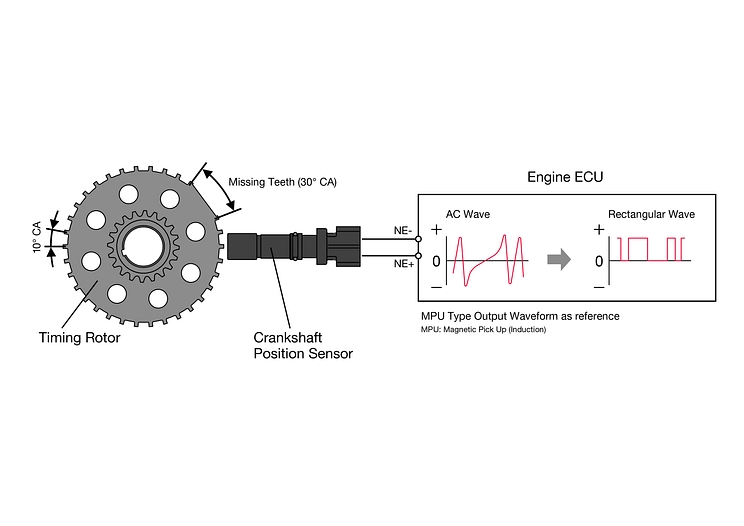
The crankshaft position sensor is attached to the engine block facing the timing rotor on the crankshaft. It counts the number of teeth on the crankshaft that have passed the sensor, sending this value to the ECU which can then work out where the crankshaft is on its 360-degree rotation. The rate of positional change is used to calculate the engine’s rotational speed.
The camshaft position sensor is mounted near the cylinder head, opposite the timing rotor attached to the engine camshaft. It monitors the changing magnetic resistance from the moving magnetic field of the timing rotor; this information is used by the ECU to calculate the camshaft angle and to recognize which cylinder is firing.
Together, these components ensure the engine parts remain ‘in time’ and the engine operates smoothly and efficiently. With both Magnetic Resistant Element (MRE) type and Magnetic Pick-Up (MPU) type sensors available, DENSO offers a comprehensive range of OE-quality sensors to the aftermarket.
Features and benefits
-
Variety of sizes and designs available, across inductive and semiconductor types.
-
Excellent reliability, with simple and problem-free connections and high temperature resistance.
-
Guaranteed first-time fit and superior performance.
-
The DENSO name is associated with high quality and low return rates.
Multiple use cases covered
With a wide range of MPU and MRE-type sensors available, there are DENSO sensors available to fit every need, from high precision to high temperature resistance.
Smaller and easier
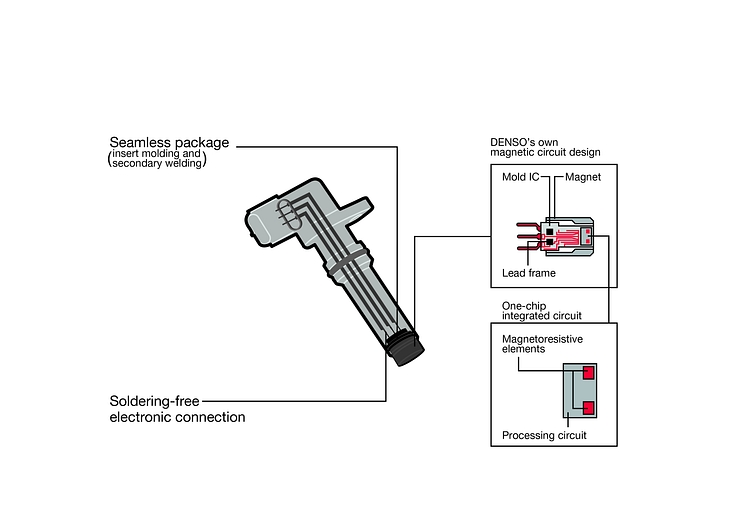
Sensors are built to be compact, integrating multiple parts on one chip. They also offer seamless packaging and solder-free connections for ease of installation.
Built to last
A thin but strong body with a smaller air gap means DENSO sensors retain excellent durability. They are designed to minimise faults and returns.
Types and characteristics
DENSO offers two main types of sensor, across both crankshaft sensor and camshaft sensor functions.
Camshaft and crankshaft sensors types
MPU sensor (inductive type)
Widely used, highly precise sensor. Primarily consists of a body, collar, magnet, and coil. O-rings and collar swaging protect the coil from contamination.
Many variations are available to meet different engine specifications and rotor sizes. Direct connection type and lead wire type in range.
MRE sensor (semiconductor type)
A compact sensor that combines the detection element and processing circuit on one chip. Magneto-resistive element powers high signal-to-noise ratio, enabling excellent detection accuracy. In turn, this enables a greater degree of fuel efficiency and lower emissions.
Characteristics
MRE-type sensors use DENSO’s own magnetic circuit design, with a one-chip integrated model. MPU-type sensors are available as either direct-connection or lead-wire sensors, maximising car parc coverage.
Installation and fault finding
Correct installation, maintenance and monitoring of DENSO camshaft and crankshaft sensors will keep them operating to their fullest potential, powering efficient engine performance.
Installation
Make sure you install camshaft and crankshaft sensors safely, consulting OEM guidelines or diagnostic tools where appropriate.
Take care – camshaft and crankshaft sensors are a delicate piece of hardware that can be damaged when installing. Do not allow ingress of moisture, chemicals or other foreign materials; do not place sensors in areas where excess static discharge is continuously applied; and do not place sensor tips close to each other or to a magnet.
Disconnect the connector and wiring if it exists. Remove the screw(s). Remove the sensor.
Install the new sensor and screw(s) according to the tightening torque value specified by the vehicle manufacturer. Connect the connector and sensor wiring if needed. Turn the engine on and check that the system works properly.
Fault finding
Regular maintenance and replacement where necessary is essential to keeping camshaft and crankshaft sensors functioning optimally.
Scratches on the magnetic surface of the sensor
Foreign material on the magnetic surface of the sensor
Exposure to significant high heat
Wear and tear in the sensor wiring
Stalling after starting, or infrequently during vehicle operation
The vehicle accelerates inconsistently
The vehicle occasionally loses power or misfires
Intermittent starting or no start at all
The engine light turns on
Using a DENSO diagnostic tool, check for an error code in the ECU (P0335-P0349)
During cranking, use the scan tool oscilloscope function to inspect the sensor’s voltage waveform. If there is a normal waveform, inspect for faulty ECU, open or short circuit problems in wiring. If there is no waveform, inspect for faulty sensor.
Replace the sensor, making sure the timing rotor and sprocket do not touch the magnetic surface of the sensor (select correct thickness shim and/or assure proper clearance).
Catalogues and marketing materials
To find out more about Camshaft and crankshaft sensors browse the Downloads Area section. Click here.