


Starter troubleshooting
Starter overview
Since a vehicle’s combustion engine cannot start unaided, an external force is required to provide the rotational speed required, so a starter is used to initiate the operation. The starter activates a built-in motor using the vehicle’s battery as the power source to start the engine. Unlike normal DC motors, the starter is only used for a short time, so despite producing a large output, is designed to be very small.
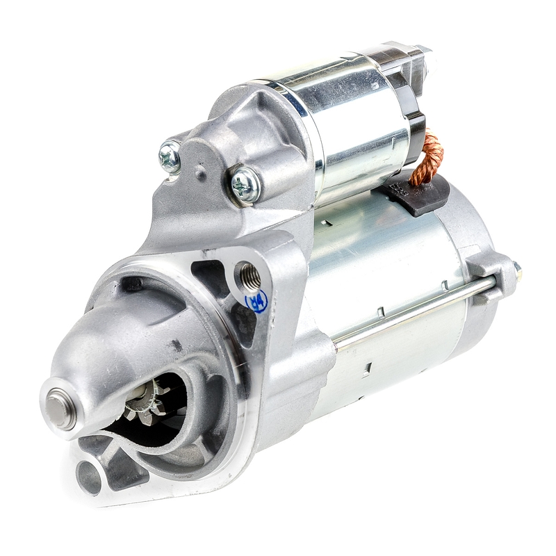
The starter primarily consists of an armature, pinion gear, magnetic switch, drive lever and overrunning clutch, and its construction can be broadly divided into the ‘motor section’ and the ‘engine engagement and disengagement mechanism’.
The starter has progressed in tandem with vehicle design, into a compact, lightweight, high-performance device. The 1970s saw the introduction of the pinion shift type (direct-drive) starter, followed in the 1980s by the development of the offset gear reduction type starter that incorporated a deceleration mechanism. By the 1990s, the reduction type starter utilised a high deceleration ratio to create an even more compact and lightweight solution. Making further reductions in size and weight, the planetary type starter was developed in the first decade of the 21st century, incorporating a planetary gear and ferrite magnets.
What can go wrong and how to fix it
First, the battery must be fully charged (12.6 volts or above) and the battery cables, terminals and case in good and clean condition. So, start with a visual inspection and battery state of charge before inspecting the starting system.
Starting system current draw test
Connect voltmeter positive lead to the positive battery terminal and the voltmeter negative lead to the negative battery terminal, then connect the clamp-on amp probe pickup around the battery cable. While cranking the engine, which should normally be approximately 200-250 rpm, check the voltage and current readings. The current draw should be at or below the maximum limit that is specified by the vehicle manufacturer’s repair manual, whereas the cranking voltage should be at or above the minimum limit that is specified by the vehicle manufacturer’s repair manual, but is usually approximately 9.6 volts at 20-25°C
High current draw and low cranking speed usually indicate a defective starter. This can be caused by starter motor layer short, worn brushes or bushings, mechanical blockage. High current draw may also be caused by engine problems. A low cranking speed with low current draw, but high cranking voltage, usually indicates excessive resistance in the starter circuit.
High resistance in starter positive or negative side reduces current to the starter motor and causes slow cranking speed or hard cranking. High resistance in starter control circuit reduces current to the magnetic switch and causes improper operation or no operation at all. Every wire, cable and terminal connection has the potential to create excessive voltage loss that can affect starter performance. Checking the voltage drops provide helpful tips to find hidden problems that can cause a starting system problem.
Positive side voltage drop test
Connect the voltmeter positive lead to the positive battery terminal and the voltmeter negative lead to the battery terminal on the starter, then, while cranking the engine, check the voltage reading. If the voltage drop is 0.5 volts or less, the resistance is acceptable, but if it’s more than 0.5 volts, there is excessive resistance, which could be caused by a damaged battery cable, poor connection at the battery or starter terminal, or a defective magnetic switch.
Clean and tighten the battery terminals and perform the following voltage drop tests to isolate the cause and repair the fault.
First, while cranking the engine, check the voltage drop between positive battery terminal and cable connection. Connect the voltmeter positive lead to the positive battery terminal and the voltmeter negative lead to the battery cable clamp. The acceptable cable connection voltage drop should be 0 volts.
Second, while cranking the engine, check the voltage drop of positive battery cable. Connect the voltmeter positive lead to the clamp on the positive battery cable and the voltmeter negative lead to the end of the cable at the starter. The acceptable battery cable voltage drop should be 0.2 volts or less.
Finally, while cranking the engine, check the voltage drop across the magnetic switch. Connect the voltmeter positive lead to the positive battery terminal on the starter and the voltmeter negative lead to the starter motor terminal. The acceptable voltage drop across the magnetic switch should be 0.3 volts or less.
Negative side voltage drop test
Connect the voltmeter positive lead to a clean spot on starter motor housing and the voltmeter negative lead to the negative battery terminal. While cranking the engine, check the voltage reading. If the voltage drop is 0.2 volts or less the resistance at negative side is acceptable, but if drop is more than 0.2 volts, there is excessive resistance, which could be caused by poor starter mount on the vehicle, poor battery ground or a loose connection.
So, check if the starter is properly installed, make sure all the ground points/straps between the engine and chassis are secured, and clean and tighten the battery terminals and perform the following voltage drop tests to isolate the cause and repair the fault, similar to the positive side tests.
First, while cranking the engine, check the voltage drop between negative battery terminal and cable connection, which should be 0 volts.
Second, while cranking the engine, check the voltage drop of negative battery cable from the battery to the engine block, which should be 0.2 volts or less.
Finally, while cranking the engine, check the voltage drop between the starter housing and the engine block, which should be 0.2 volts or less.
Starting system control circuit voltage drop test
If the battery is in good condition, but the starter does not crank the engine, the problem could be a poor ignition switch connection or excessive resistance in the starter control circuit that can reduce the voltage available to the magnetic switch. The pinion gear not engaging or engaging incorrectly are both symptoms of this problem.
Excessive resistance could occur at the ignition switch contacts, park/neutral start switch, clutch start switch or the circuit wiring and connections. So, perform the following voltage drop tests to isolate the cause and repair the fault:
Connect the voltmeter positive lead to the positive battery terminal and the voltmeter negative lead to the magnetic switch terminal on the starter. Put the gear shift selector in park or neutral, for vehicles with automatic transmission, or depress the clutch pedal and crank the engine and observe the voltage reading on the voltmeter. Also, check the voltage drop across the ignition switch and neutral start switch or clutch start switch, to know whether the readings are within the appropriate vehicle manufacturer’s specifications, and adjust or replace the defective switches as necessary.
Another possible cause of the starting system problems could be a defective starter relay (if equipped),so perform a continuity test with the relay de-energised and energised. If any of these tests do not match the vehicle manufacturer’s specified results, replace the starter relay.
An alternative voltage drop method
Checking the voltage drop across each component of the starting circuit is an alternative method to locate the cause of an excessive voltage drop. Leave the voltmeter positive lead connected to the positive battery terminal and move the voltmeter negative lead back through the circuit toward the battery. Continue to test each connection while cranking the engine until a noticeable decrease in voltage drop is detected. The cause of the excessive voltage drop will be located between that point and the preceding one.
Does the starter turn the engine too slowly?
The battery must be fully charged (12.6 volts) and the battery cables, terminals and case in good, clean condition, including the frame and body ground connections and connections at the starter motor and magnetic switch.
Excessive engine oil viscosity, particularly in cold conditions, will reduce the ability of the engine to rotate. This increase in engine drag will be transmitted to the starter during starter engagement, reducing its performance capability.
In addition, modifications to the engine can change the operating characteristics of the engine and potentially introduce more force acting against the starter, which will mean it will need to be replaced with one to match.
Does the starter fail to crank the engine?
The starter is designed to turn at a specified rotational speed to crank the engine, but if there is a high resistance somewhere in the starting control circuit, or the battery connections or cables are corroded or dirty, this will cause the starter to turn too slowly.
Does the starter rotate without rotating the engine?
If the starter is rotating but not the engine, check all teeth on the flywheel or flexplate ring gear to see if they are excessively worn, damaged or missing, by looking through the inspection plate on the bell housing or starter mounting port.
A defective starter drive assembly could cause similar symptoms as a damaged flywheel or flexplate. So, if the starter pinion gear meshes properly, but does not rotate, the starter should be inspected for mechanical wear or damage.
Does the magnetic switch make operating noise when activated?
If clicking is heard when activating the starter control circuit and the starter does not rotate, the magnetic switch may not be receiving the voltage necessary to be fully activated. Check the starter control circuit for failed or damaged components and wiring, and loose, dirty or corroded connections.
If, however, the magnetic switch is receiving proper voltage, it may have burnt contacts. Follow the vehicle manufacturer’s procedures and safety precautions to inspect the starter.
If the magnetic switch does not make any operating noise, it may be a defective pull-in coil or plunger. So, again, follow the vehicle manufacturer’s procedures and safety precautions to inspect the starter.
What does continuous or prolonged cranking cause?
Low battery voltage results in excessive current flow to the starter motor.
Starter motor commutator is overheated, bars on commutator lift from insulator.
Damage to brushes and/or brush holder assembly occurs.
What does occur if the ignition key is excessively held in start position?
Starting control circuit stays closed, causing burnt magnetic switch main contacts.
Starter pinion gear rotates at flywheel speed (engine speed), which causes overrunning.
Commutator bars separate and cause damage to brushes, brush holder assembly and commutator.
What are the causes of pinion gear teeth damage and meshing problems?
A new starter is fitted to a flywheel that has damaged or worn ring gear teeth.
Driver fault (engagement of the ignition key while the engine is operating).
Mechanical problem (ignition switch or starter magnetic switch main contacts stuck closed).
What are the key aspects when selecting an aftermarket starter?
Vehicle manufacturers specify numerous OE part numbers for their starter motors, which is why aftermarket suppliers consolidate their range as much as possible. A replacement starter does not have to look like the original unit, but it must match the power output and fitting interface dimensions.
The most important features are:
Long lifespan and maintenance-free.
Fitting interface dimensions such as fixing hole locations, diameters, thread sizes, terminal locations, etc., as well as the number of pinion teeth and the direction of rotation.
Power output capacity should meet the vehicle’s requirements
Caution: Never use a starter with lower power output capacity for a vehicle that requires a starter with higher capacity. For example, do not use a 1.4 kW rated starter for a vehicle that requires a 2.0 kW rated starter, as excessive current flow will cause premature starter failures.
DENSO starters
Since introducing its first commercial automotive starter motors in the early 1960s, DENSO has poured its world-leading engineering expertise into developing smaller, lighter units that can maintain the highest possible output. In 2001, for example, DENSO introduced the world’s first Planetary Reduction Segment Conductor Motor (PS) Starter featuring a square conductor in the armature coil.
Key Facts
- Completely new, boxed items (no reman) and no core surcharge.
- Range includes Pinion Shift (GA type), Reduction (R and RA types), Planetary (P, PA, PS and PSW types) and Stop-Start (AE, TS and PE types).
- Maximum efficiency by offering small size and light weight units while delivering the highest outputs.
Further details of the DENSO Aftermarket programme are available online at: www.denso-am.eu